 ASME Steam Table Library
 ASME Steam Table Library
The Westinghouse ASME Steam Table library has been in existence for many years. This library of well-tested functions is available for those who need to perform calculations involving the various properties of steam. Users are responsible (as always) for verifying the accuracy of their results.
 Section Title


 1.0     Introduction

 2.0     Validation of the ASME Steam Property
         Procedures

 3.0     Basis for the Westinghouse 7600 Steam
         Property Procedures and Certain Limitations

 4.0     Use of the ASME Steam Property Procedures

     4.1 Nomenclature
     4.2 The Three Calculational Regions
     4.3 Regions of Applicability
     4.4 Description of Steam Property Functions
         CONDL  CONDV  CPL     CPV
         CRFLO  CRVEL  HCL     HSL
         HSS    HSSICL HSSISS  HSV
         PRLIQ  PRSTM  PSL     PSV
         SSL    SSSICL SSSISS  TSL
         TSLH   VCL    VISL    VISV
         VSL
     4.5 Input Argument Limits for Specific Enthalpy, H

     4.6 Input Argument Limits for Specific Entropy, S

     4.7 Procedures Grouped by Output Property - Table 1

     4.8 Procedures Grouped by Region - Table 2

     4.9 Alphabetic Listing of Steam Property Procedures - Table 3

 5.0     References

 6.0     STEAMV67 routine should be called to document the
         pedigree of the library being used.

 7.0     Document Revision Record
This document describes the Westinghouse ASME Steam Table FORTRAN library procedures. The library is a set of well-tested functions that dates back many years. It is available for those who need to work with calculations involving the various properties of steam.
Note that this library is all double precision.
Users are responsible (as always) for verifying the accuracy of their results.
The fastest way to look up a specific procedure's information is to go to one of the hyper-text tables in sections 4.7, 4.8, and 4.9, and click on a routine name.
The following quotations, taken directly from the "1967 ASME Steam Tables" published by the American Society of Mechanical Engineers, are thought to be of significant value both as background, and for proper use of the ASME Steam Table subroutines. The entire introduction is taken from the "1967 ASME Steam Tables" reference, except for the headings for Sections 1.1, 1.2. and 1.3.
The publication of these new ASME Steam Tables represents the culmination of an ASME project which had its origin in 1954 when, at the Fourth International Conference on Properties of Steam held in Philadelphia, Pa., it was decided that the time had come to update our knowledge of the thermodynamic properties of steam. Fortunately, the Society was able to take advantage of the experience of a number of its members who were involved in a similar venture more than thirty years earlier.
Just as occurred previously, the project required fund raising, identification and technical supervision of new experimental research, extensive international cooperation, and the adoption of internationally accepted skeleton tables. This time, however, the demand for standardization of design and performance calculations could not be satisfied by skeleton tables alone. International agreement had to be reached on a set of equations which would reproduce these skeleton tables, provide a suitable interpolation scheme, and yet give reasonable computer efficiency when incorporated in the already complex computer programs used day after day for design and performance calculations.
The First International Conference on Properties of Steam, London, England, 1929, concerned itself with a detailed examination of the tables of specific volume and enthalpy submitted by the various national delegations. The skeleton tables compiled at that conference served as the basis for the 1930 ASME Steam Tables, prepared by Professor J. H. Keenan and published by ASME. This conference recognized that considerable additional measurements would be required before a truly satisfactory representation of these properties could be agreed upon.
Progress was reviewed at the Second International Conference, held in Berlin, Germany, in 1930, at which time, significant modifications were made in the skeleton tables. The time, however, was not ripe for full agreement. Such agreement was reached in 1934 at the Third International Conference held in Washington, D.C., Cambridge, Mass., and New York, N.Y., with the adoption of skeleton tables giving the specific volume and enthalpy along the saturation line and at round values of temperature and pressure for the compressed liquid and superheated vapor. In addition, each entry in the tables had associated with it a tolerance so that the two values would "constitute a criterion, internationally agreed upon, by which, the reliability of steam tables may be judged". The skeleton tables and the experimental measurements which led up to them served as the basis for a number of publications, the most prominent of which was the Keenan and Keyes Steam Tables which had served as the vade mecum of engineers these past 30 years.
The need was recognized for continued research on properties of steam and water by the Third International Conference, to an extent that solicitations and even recorded assurances from various delegations and institutions assured that the work on steam would be continued and extended.
The plan to hold a Fourth International Conference in Prague, Czechoslovakia gave way in time to more pressing problems brought on by the Second World War. Almost twenty years elapsed before the thermodynamic properties of steam again became an active concern of the Society and the international scientific and engineering community. When the Fourth International Conference was held in Philadelphia, PA in 1954, it was evident that technological advances made in intervening years would require thermodynamic information outside of the temperature and pressure range of the existing steam tables. The Society established a research committee on the Properties of Steam, and charged it with the task of arranging for new research and reestablishing the program of international coordination, which had proved so fruitful two decades earlier. The Society also accepted the invitation to serve as the permanent Secretariat for the International Conferences on Properties of Steam.
By this time, interest had developed in Japan and the U.S.S.R. in thermodynamic tables for steam having the status of an international standard. Moreover, a considerable body of new experimental measurements had been reported by a number of institutions in the Soviet Union. Thus, at the time of the Fifth International Conference, London, 1956, it was evident that the work of examining the published data and supervising the then current research could be handled best by national commissions from the four countries in which the major experimental research was being carried on. It was further agreed, that the national Commissions (Federal Republic of Germany, United Kingdom. Union of Soviet Socialist Republics, and the United States) would constitute the International Coordinating Committee - the working group of the Fifth International Conference.
The labors of the International Coordinating Committee were rewarded at a plenary session of the Sixth International Conference on the Properties of Steam, New York, N. Y., 1963. when the tables were adopted as "The International Skeleton Tables of 1963". The temperature range of the skeleton tables is from 0 to 800 C and the pressure extends to 1000 bars - a considerable extension over the range of the 1934 Skeleton Tables. Where new experimental data reflected refined experimental techniques, they are in turn, reflected in the narrower "tolerance" limits of the new tables. The skeleton tables adopted by 16 member nations of the Sixth International Conference, are the bases for the equations from which these ASME Steam Tables have been computed.
Long before the work of the International Coordinating Committee was completed, it was clear to most members of the working groups that the skeleton tables alone did not insure the degree of reproducibility originally envisioned for design and performance calculations owing to the relatively coarse grid of the skeleton tables and to the requirements of performing numerical differentiation and integration. It became important to ensure that each country handled the numbers in the same way when it came to compiling detailed tables such as the following, or, when incorporating the skeleton tables into a computer program for design and performance calculations. The Sixth International Conference was cognizant of this problem and established an International Formulation Committee (IFC) to:
"Develop at the earliest practical date a formulation for use with computers of the properties of steam as they are represented by the International Skeleton Tables of 1963. This formulation shall provide values that are, at all points, within the tolerances stated in the International Skeleton Tables of 1963, and shall be thermodynamically consistent."
After two years of sustained effort, during which delegates from Japan and Czechoslovakia joined those of the Federal Republic of Germany, United Kingdom, United States of America, and the Union of Soviet Socialist Republics, a conference was held in Prague, at which agreement was reached concerning the form and characteristics of the equations which would meet the requirements laid down by the Sixth International Conference. A year later (March 1966), the IFC met in Glasgow, Scotland. After much deliberation, unanimous agreement was reached among the six national delegations on a formulation, which, after some post-conference modifications. was recommended to the members of the Sixth International Conference.
While it was the general feeling of the IFC that the formulation did indeed satisfy the requirement for international standardization of steam tables for industrial use, it left much to be desired as a definitive equation of state for steam; thus, The "1967 IFC Formulation for Industrial Use: A Formulation of the Thermodynamic Properties of Ordinary Water Substance." Several of the countries participating in the Sixth International Conference are using this formulation to prepare more detailed tables for steam and water. This formulation is the basis for the thermodynamic tables and figures in these new ASME Steam Tables.
The Sixth International Conference expanded the scope of its activity by establishing a panel of experts to develop skeleton tables for transport properties (viscosity and thermal conductivity of steam and water). That panel completed its work at a meeting in Paris, France, in June 1964 and the transport properties given here are based on the skeleton tables and the empirical equations which they developed.
The canonical functions provide the definitive expression of the formulation. The derived functions are for practical use and are secondary to the canonical functions.
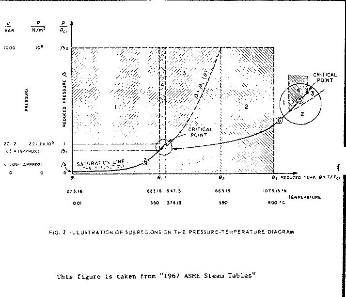
The formulation presented herein describes the thermodynamic properties of ordinary water substance throughout the whole of the region that extends pressure from the ideal-gas limit (at zero pressure) to a pressure of 10**8 N/m**2 (1000 bar), and that extends in temperature from 273.16 K (0.01 C) to 1073.15 K(800 C).
Two computer programs which have evolved from this study are:
             C=HSS(P,T,S,V) to calculate S using P and T

             H=HSSISS(P,S,T1,V1,X) to calculate the enthalpy, H, using P and S.
*See Section 4 for a description of usage of the steam property sub-programs. Specifically see sections 4.4.9 and 4.4.11 for descriptions of HSS and HSSISS, respectively.
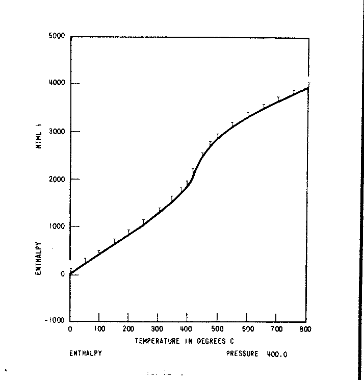
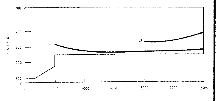
Note that in Figure 1, an example of such a plot, the T's of the skeleton table values rest on the line generated by the periods, and hence agreement is perfect.
Similar plots are produced by fixing temperature at each of the skeleton values, and varying pressure in small increments, over the entire pressure range.
For purposes of Quality Assurance, checksums are calculated by summing plotted results for each fixed pressure and temperature. A total checksum for all properties is also calculated.
Microfiche print and plot output of this program is available from Customer Services.
 2.3.1  For Specific Volume

        VSL,HSV,VCL,HSS,HSSISS,SSSISS,CPV

 2.3.2  For Specific Enthalpy

        HSL,HCL,HSSICL,HSS,HSV,HSSISS

 2.3.3  For Specific Entropy

        SSL,HCL,SSSICL,HSS,HSV,SSSISS

 2.3.4  For Thermal Conductivity

        CONDL,CONDV

 2.3.5  For Viscosity

        VISL,VISV

 2.3.6  For Specific Isobaric Heat Capacity

        CPL,CPV

 2.3.7  For Temperature

        TSL,TSLH,HSV,HSSICL,HSSISS,SSSICL,SSSISS

 2.3.8  For Pressure

        PSL,PSV

 2.3.9  For Prandtl Number

        PRLIQ and PRSTM

 2.3.10 CRVEL which calculates critical velocity.

 2.3.11 CRFLO which calculates Critical Mass Flow Rate.

 2.4    The following outputs have not been validated:

 2.4.1  Isentropic Exponent from CRVEL.

 2.4.2  Quality, as output by HSSISS and SSSISS.
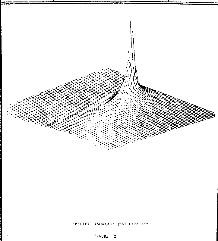
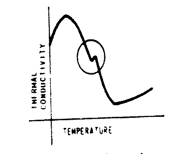
The calculation of heat capacity by numerical differentiation demonstrates two possible characteristics which must be considered for all of the ASME steam properties:
The specific volume V1 which is calculated by
C = HSS(P,T.S,V1) to calculate V1
and the specific volume V2 which is calculated by
             Q = HSS(P,T,S,V1)           to calculate S
                                         for P and T.

             C = HSSISS(P,S,T1,V2,M)     using above
                                         output S to
                                         calculate V2.
agree to six decimal places. This example demonstrates a rather
remarkable consistency of the results produced by HSS and HSSISS, a
consistency which has been found to be generally true of the ASME
sub-programs.

- P[min], P[max]
- The minimum and maximum pressures for which a property may be calculated. For pressures outside this range, the value of the property is undefined by the ASME tables.
- T[min], T[max]
- The minimum and maximum temperatures for which a property may be calculated. For temperatures outside this range, the value of the property is undefined by the ASME tables.
- P[sat]
- Saturation pressure for a given temperature
- T[sat]
- Saturation temperature for a given pressure
- P[crit], T[crit]
- Critical point pressure and temperature (3208.234 psia, 705.47 F).
- CP
- Specific Isobaric Heat Capacity, BTU/lb-F
- FC
- Critical Flow, lb/hr-in**2
- H
- Specific Enthalpy, BTU/lb
- K
- Thermal Conductivity, BTU/hr-ft-F
- P
- Pressure, psia
- PR
- Prandtl Number
- S
- Specific Entropy, BTU/lb-F
- T
- Temperature, F
- V
- Specific Volume, ft**3/lb
- VC
- Critical Velocity, ft/sec
- VISC
- Viscosity, lb/ft-sec
- X
- Quality, %/100
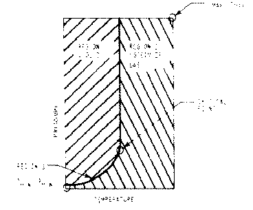
            T[min] .le. T .le. T[crit]
                      and
      and   P[sat](T) .le. P .le. P[max]

            Note that Region 1 includes the liquid side of Region 3.
            P[min] .le. P .le. P[max]
                      and
             T[sat](P) .le. T .le. T[max]   when  P .le. P[crit]
            T[crit](P) .le. T .le. T[max]   when  P   >  P[crit]
Note that Region 2 includes the steam/gas side of Region 3.
It is generally true that functions with two input arguments and which end in L, must be used to compute property values in Region 1. Similarly, functions with two input arguments and which end in S or V, must be used in Region 2.
In the descriptions which follow, Definition and Purpose define input and output arguments of the function. When more than one variable appears on the left of the = sign, the first variable is the function value, and the remaining variables are output arguments. The values in parentheses to the right of the = sign are the input arguments.
- 4.5.2.1
- For a temperature T in Region 2 such that T .le. T[crit], let P[sat] = PSL(T). Then HSS(P[sat],T) .le. H .le. HSS(P = .01,T). The approximate magnitude of these limits may be obtained by dividing results of Table 1.3 (Appendix 4, Reference 1) by 2.326.
- 4.5.2.2
- For a temperature T in Region 2 such that T > T[crit], HSS(P[max],T).le. H .le. HSS(P=.01,T). The approximate magnitude of these limits may be obtained by dividing results of Table 1.3 (Appendix 4, Reference 1) by 2.326.
- 4.6.2.1
- For a temperature T in Region 2 such that T .le. T[crit], let P[sat]=PSL(T), and S1 be the value of specific entropy given by calling HSS(P[sat],T). Let S2 be the value of specific entropy given by calling HSS(P = .01,T). The approximate limits on the specific entropy S are S1 .le. S .le. S2. Values for S1 and S2 may be obtained by dividing results of Table 8 (Appendix 3, Reference 1) by 4.1868.
- 4.6.2.2
- For a temperature T in Region 2 such that T > T[crit], let S1 and S2 be values of specific entropy obtained by calling HSS(P[max],T) and HSS(P= .01,T). Then S1 .le. S .le. S2. Approximate values of S1 and S2 may be obtained by dividing results of Table 8 (Appendix 3, Reference 1) by 4.1868.
| Output Property | Region | Function | Input Arguments |
|---|---|---|---|
| Specific Enthalpy | Saturated Liquid | H=HSL(T) | T |
| Saturated Vapor | H=HSV(P,T,S,V) | P | |
| Liquid | H=HCL(P,T,S) | P,T | |
| Liquid | H=HSSICL(P,S,T) | P,S | |
| Steam/Gas | H=HSS(P,T,S,V) | P,T | |
| Steam/Gas | H=HSSISS(P,S,T,V,X) | P,S | |
| Specific Entropy | Saturated Liquid | S=SSL(T) | T |
| Saturated Vapor | H=HSV(P,T,S,V) | P | |
| Liquid | H=HCL(P,T,S) | P,T | |
| Liquid | S=SSSICL(P,H,T) | P,H | |
| Steam/Gas | H=HSS(P,T,S,V) | P,T | |
| Steam/Gas | S=SSSISS(P,H,T,V,X) | P,H | |
| Prandtl Number | Liquid | PR=PRLIQ(P,T) | P,T |
| Steam/Gas | PR=PRSTM(P,T) | P,T | |
| Pressure | Saturation Line | P=PSL(T) | T |
| Saturated Vapor | P=PSV(S) | S | |
| Specific Heat | Liquid | CP=CPL(P,T) | P,T |
| Steam/Gas | CP=CPV(P,T,V) | P,T | |
| Specific Volume | Saturated Liquid | V=VSL(T) | T |
| Saturated Vapor | H=HSV(P,T,S,V) | P | |
| Liquid | V=VCL(P,T) | P,T | |
| Steam/Gas | CP=CPV(P,T,V) | P,T | |
| Steam/Gas | H=HSS(P,T,S,V) | P,T | |
| Steam/Gas | H=HSSISS(P,S,T,V,X) | P,S | |
| Steam/Gas | S=SSSISS(P,H,T,V,X) | P,H | |
| Steam Quality | Steam/Gas | H=HSSISS(P,S,T,V,X) | P,S |
| Steam/Gas | S=SSSISS(P,H,T,V,X) | P,H | |
| Temperature | Saturated Liquid | T=TSLH(H) | H |
| Saturation Line | T=TSL(P) | P | |
| Saturated Vapor | H=HSV(P,T,S,V) | P | |
| Liquid | H=HSSICL(P,S,T) | P,S | |
| Liquid | S=SSSICL(P,H,T) | P,H | |
| Thermal Conductivity | Liquid | K=CONDL(P,T) [see note 2] | P,T |
| Steam/Gas | K=CONDV(P,T) [see note 2] | P,T | |
| Viscosity | Liquid | VISC=VISL(P,T) | P,T |
| Steam/Gas | VISC=VISV(P,T) | P,T |
| Region | Function | Input Arguments | Calculated Properties |
|---|---|---|---|
| Liquid (Region 1) | K=CONDL(P,T) [see note 2] | P,T | Thermal Conductivity |
| CP=CPL(P,T) | P,T | Specific Isobaric, Heat Capacity | |
| H=HCL(P.T,S) | P,T | Enthalpy, Entropy [see note 3] | |
| H=HSSICL(P,S,T) | P,S | Enthalpy, Temperature | |
| PR=PRLIQ(P,T) | P,T | Prandtl Number | |
| S=SSSICL(P,H,T) | P,H | Entropy, Temperature | |
| V=VCL(P,T) | P,T | Specific Volume | |
| VISC=VISL(P,T ) | P,T | Viscosity | |
| Steam/Gas (Region 2) | K=CONDV(P,T)[see note 2] | P,T | Thermal Conductivity |
| CP=CPV(P,T,V) | P,T | Specific Isobaric, Heat Capacity, Specific Volume | |
| H=HSS(P,T,S,V) | P,T | Enthalpy, Entropy, Specific Volume | |
| H=HSSISS(P,S,T,V,X) | P,S | Enthalpy, Temperature, Specific Volume, Quality | |
| PR=PRSTM(P,T) | P,T | Prandtl Number | |
| S=SSSISS(P,H,T,V,X) | P,H | Entropy, Temperature, Specific Volume, Quality | |
| VISC=VISV(P,T) | P,T | Viscosity | |
| Saturation Line (Region 3) | H=HSL(T) | T | Enthalpy |
| H=HSV(P,T,S,V) | P | Enthalpy, Temperature, Entropy, Specific, Volume | |
| P=PSL(T) | T | Pressure | |
| P=PSV(S) | S | Pressure | |
| S=SSL(T) | T | Entropy | |
| T=TSLH(H) | H | Temperature | |
| T=TSL(P) | P | Temperature | |
| V=VSL(T) | T | Specific Volume |
| Sub-Program Name | Region of Application | Input/Output Specifications | Reference Section |
|---|---|---|---|
| CONDL | Region 1 (Liquid) | K=f(P,T) | 4.4.1 |
| CONDV | Region 2 (Steam/Gas) | K=f(P,T) | 4.4.2 |
| CPL | Region 1 | CP=f(P,T) | 4.4.3 |
| CPV | Region 2 | CP,V=f(P,T) | 4.4.4 |
| CRFLO | Wet or Superheated Steam | FC,DEGS=f(P,H) | 4.4.5 |
| CRVEL | Wet or Superheated Steam | VC,GAMMA=f(P,H) | 4.4.6 |
| HCL | Region 1 | H,S=f(P,T) | 4.4.7 |
| HSL | Liquid side of Region 3 Saturation | H=f(T) | 4.4.8 |
| HSS | Region 2 | H,S,V=f(P,T) | 4.4.9 |
| HSSICL | Region 1 | H,T =f(P,S) | 4.4.10 |
| HSSISS | Region 2 | H,T,V,X=f(P,S) | 4.4.11 |
| HSV | Vapor side of Region 3 | H,T,S,V=f(P) | 4.4.12 |
| PRLIQ | Region 1 | PR=f(P,T) | 4.4.13 |
| PRSTM | Region 2 | PR=f(P,T) | 4.4.14 |
| PSL | Region 3 (Saturation) | P=f(T) | 4.4.15 |
| PSV | Region 3, vapor side | P=f(S) | 4.4.16 |
| SSL | Liquid side of Region 3 | S=f(T) | 4.4.17 |
| SSSICL | Region 1 | S,T=f(P,H) | 4.4.18 |
| SSSISS | Region 2 | S,T,V,X=f(P,H) | 4.4.19 |
| TSL | Region 3 | T=f(P) | 4.4.20 |
| TSLH | Region 3, liquid side | T=f(H) | 4.4.21 |
| VCL | Region 1 | V=f(P,T) | 4.4.22 |
| VISL | Region 1 | VISC=f(P,T) | 4.4.23 |
| VISV | Region 2 | VISC=f(P,T) | 4.4.24 |
| VSL | Liquid side of Region 3 | V=f(T) | 4.4.25 |
Published by the American Society of Mechanical Engineers
Authorized by Ichimatsu Tanishita, Koichi Watanabi, and Kosei Oguchi of Keio University, in Tokyo Japan
Authorized by Ichimatsu Tanishita, Koichi Watanabi, and Kosei Oguchi of Keio University, in Tokyo Japan
A routine called STEAMV identifies the origin of the steam library being used. The first parameter identifies which FORTRAN unit number to write the output on (values less than 0 cause the output to be suppressed).
                                RECORD OF REVISIONS

 NO.        DATE

 1          08/21/87 - First release of document on-line for COS in DOCLIB.
 2          07/01/91 - First release of document on UNICOS as a PRE-RELEASE.
 3          08/20/93 - added STEAMV67 routine to allow workstation users to
                       more easily identify which library they are using.
 4          09/06/93 - Corrected f77 command example and minor carriage
                       control changes.
 5          09/06/93 - Document put onto WWW, main document is still a text file.
 6          12/19/95 - Actual conversion to HTML and added scanned graphics.